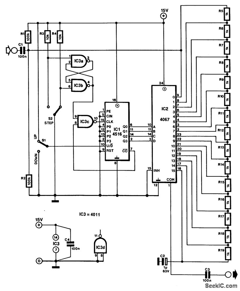
Digital volume control circuit
Description: The video discusses the following -Concept of AGC in radio receivers-Different types of AGC circuits-Working of delayed AGC circuit

Digital Volume Control Circuit
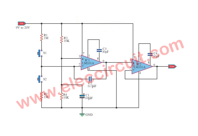
AVC - The featured circuit controls a volume line automatically. It delivers an output voltage of approximately 4 volts peak to peak. This voltage remains relatively constant by input voltages ranging from several hundred milivolts to serveral volts.
Digital Volume Control Circuit
Automatic Sound Volume Control Circuit diagram. Thread starter mildwin; Start date Jan 19, 2010; Status Not open for further replies. M. mildwin New Member. Jan 19, 2010 #1 Sir/Maam, Please, may I ask your help on how to make a automatic sound volume control circuit,from the basic steps,because this is my project study, i'm so worried the.
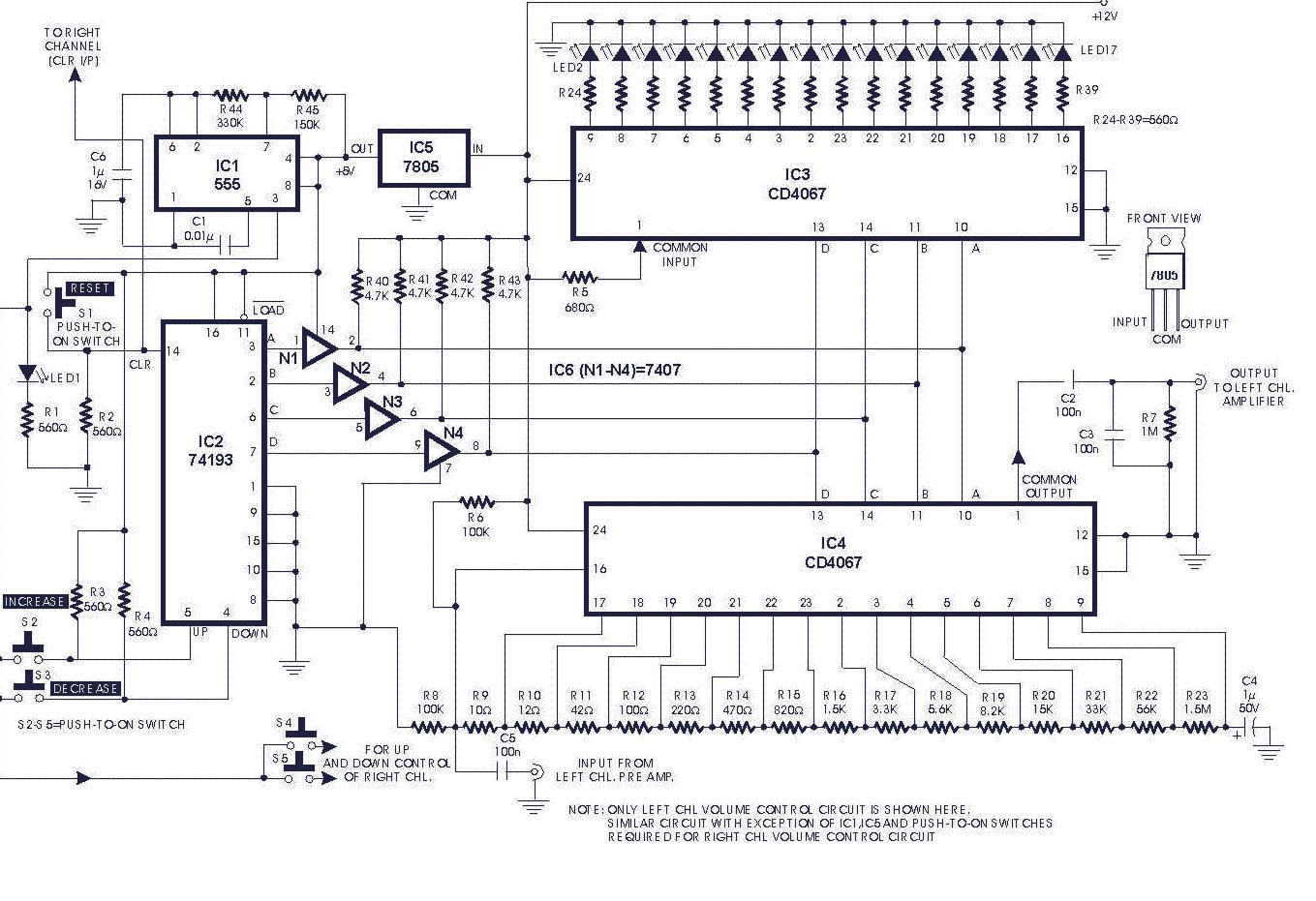
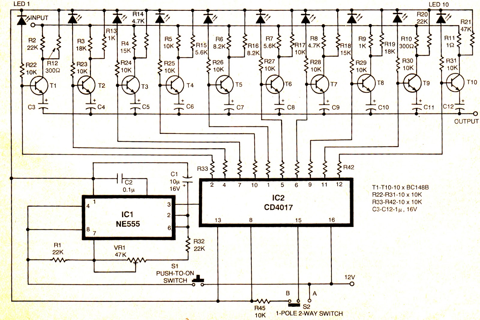
555 touch mode 10 stages volume automatic regulator circuit Control
DESCRIPTION: This circuit is uses a two stage amplification of the signals, first with a simple transistor amplifier and then with an op-amp based AGC amplifier. A condenser microphone is used at the input and a normal headset with volume controller feature is used at the output.
Digital volume control circuit
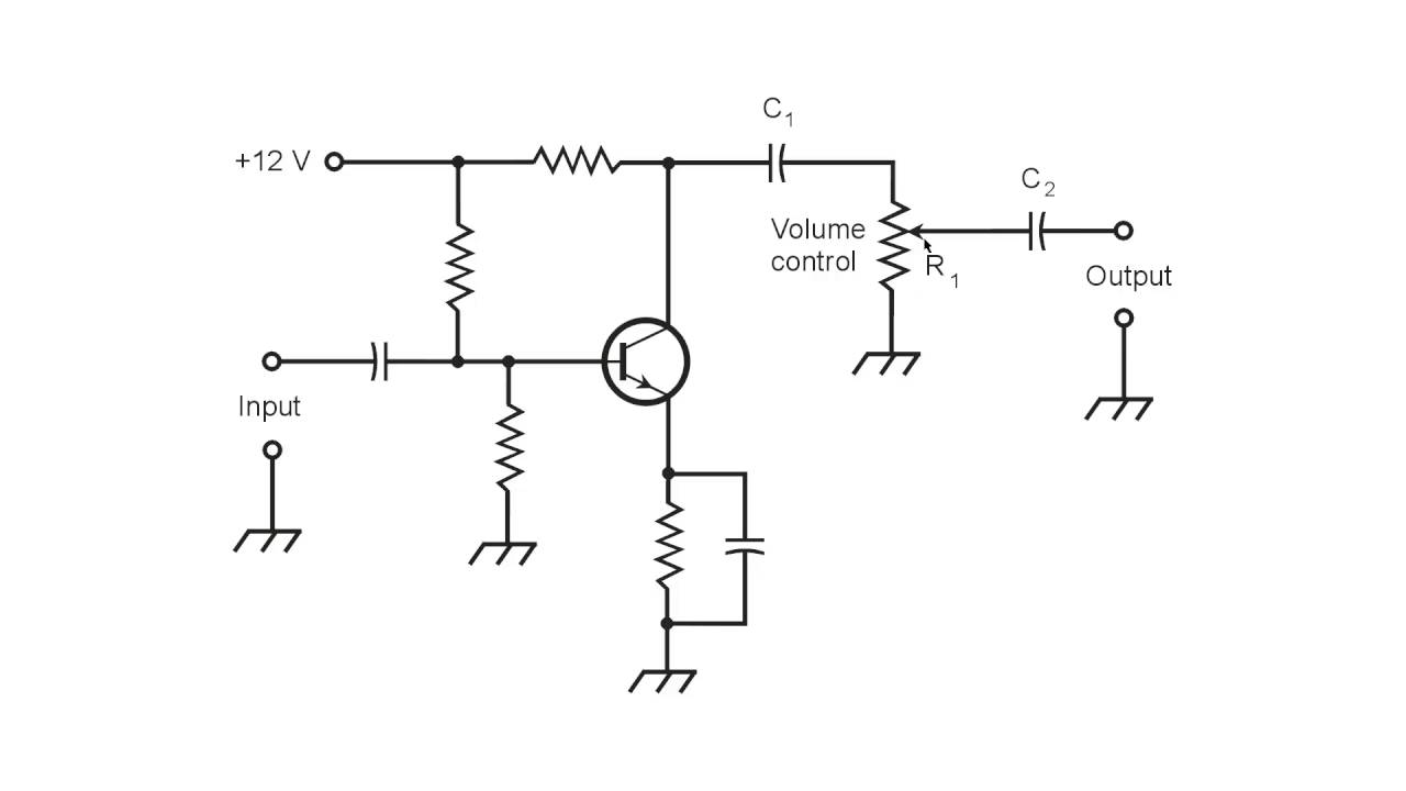
A typical volume control circuit is discussed below. The two-stage amplifier (see the figure below) uses variable resistor R2 as a volume control. Collector load resistor R1 develops transistor Q1 output signal. DC blocking capacitor C1 couples the signal to variable resistor R2 and the transistor Q2 input circuit.
Simple Digital Volume Control Circuit Diagram Wiring Diagram
12.04.2009 AGC TL071 TL072 Share this: Tweet Share More The function of this automatic volume control circuit is to amplify signals without distorting its dynamic compression. The amplitude differences in the signal are levelled off and the disturbing effect vanish. With this tehnique, overcompensation in the volume is avoided.
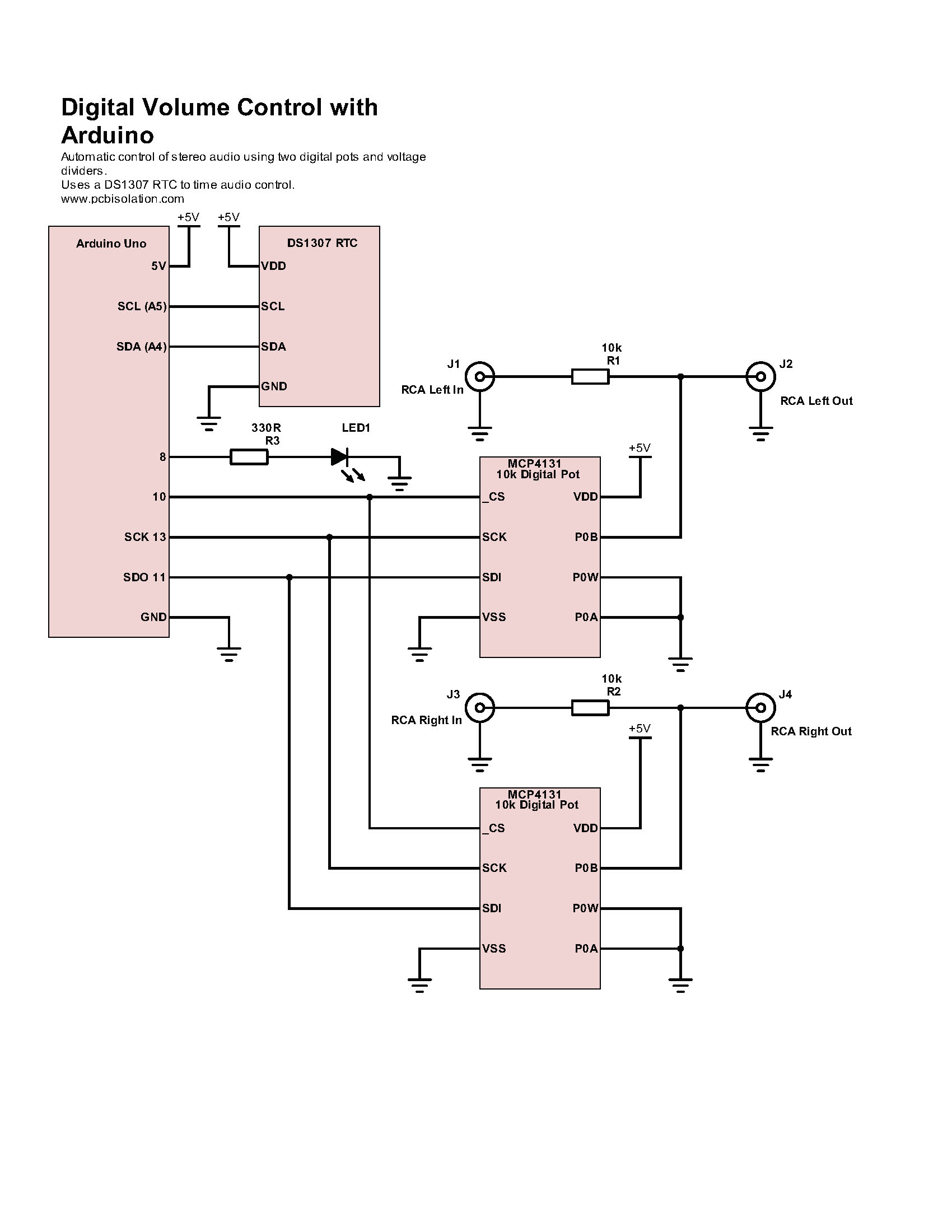
Simple Automatic Volume Control with Arduino PCB Isolation
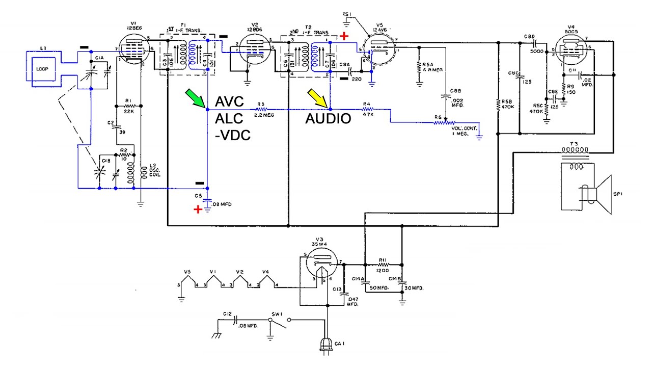
All AGC or AVC (Automatic Volume Control) circuits perform two basic funtions; The first of these is to develop a DC (Direct Current) which is proportional to the receiver input signal all the time. The AGC voltage is applied to the RF and IF stage of the receiver where it serves as a Bias voltage.In this way the AGC voltage controls the gain.
Stepped Volume Control Circuit Project
An AVC circuit diagram is usually made up of four main components. First, there's an audio gain amplifier, which amplifies or decreases the input signal. The second component is a filter, which filters out any noise so that only the intended sound is amplified.
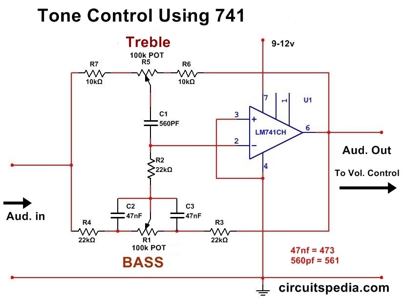
LM741 Bass/Treble & Volume Control Forum for Electronics
A volume control circuit is a wiring system found in a volume controller. Significantly, adjusting the volume assists in finding the correct volume and balance level for our audio equipment. We will discuss the volume controller circuit, its working, and the step-by-step process of making one.
A Simple Audio Volume Control YouTube
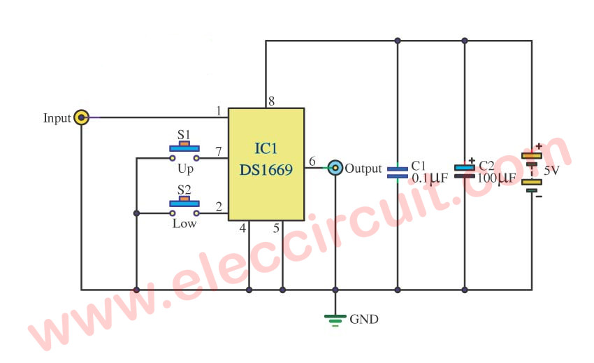
This is the circuit diagram of a digital volume controller for any sort of audio amplifiers or almost any circuit where a mechanical potentiometer is there (conditions apply). Simple and low cost, the heart of the circuit is DS 1669 digital potentiometer IC from Dallas Semiconductors.

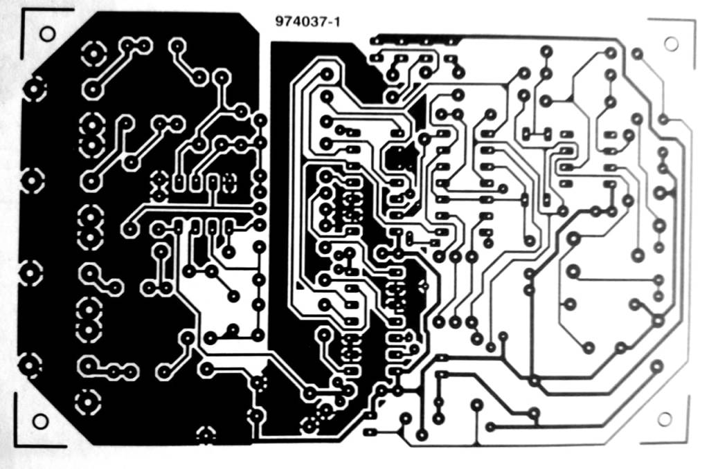
Digital volume control circuit Schematic Power Amplifier and Layout
The automatic gain control circuit AGC provides a signal with less harmonics and additional amplification, between certain limits. As a result, it eliminates those intensity differences, annoying, and of speech music, which sometimes appear on radio and television. Field effect transistors T1 is used as a variable resistance.
DIGITAL_VOLUME_CONTROL Control_Circuit Circuit Diagram
This simple AGC circuit meets that need. The circuit retains the manual gain control function, and also provides an output to drive an S-meter. Two different AGC outputs are provided. One increases level when a loud signal is received, and a second one decreases level on a loud signal.

Auto volume Schematic Power Amplifier and Layout
What does the detector tube do? What's automatic volume control? How does AVC work? Antique radio restoration.This section of our schematic shows the detecto.
Auto Volume Tone Control Circuit Diagram TRONICSpro
Switching SW1 in the other position the circuit becomes an Automatic Loudness Control and its frequency response varies in respect to the position of the control knob by the amount shown in the table below. C1 boosts the low frequencies and C4 boosts the higher ones. Maximum boost at low frequencies is limited by R2; R5 do the same at high.
Automatic Volume Level Control AVC ALC YouTube
As I have mentioned earlier, the PT2258 is an IC made to use as a 6 -Channel Electronic Volume Controller, this IC uses CMOS technology specially designed for multi-channel audio-video applications. This IC provides an I2C Control Interface with an attenuation range of 0 to -79dB at 1dB/step and comes in a 20-pin DIP or SOP package.

Volume Control Schematic Diagram Circuit Diagram
1 Design Summary The design requirements are as follows: Supply Voltage: ±15 V Input: Professional line-level audio signal (+4 dBu / 1.228 VRMS) Input impedance: 20 Ω Output: Professional line-level audio signal (+4 dBu / 1.228 VRMS)
